Summary of Ebike Components
The Parts of an Ebike System
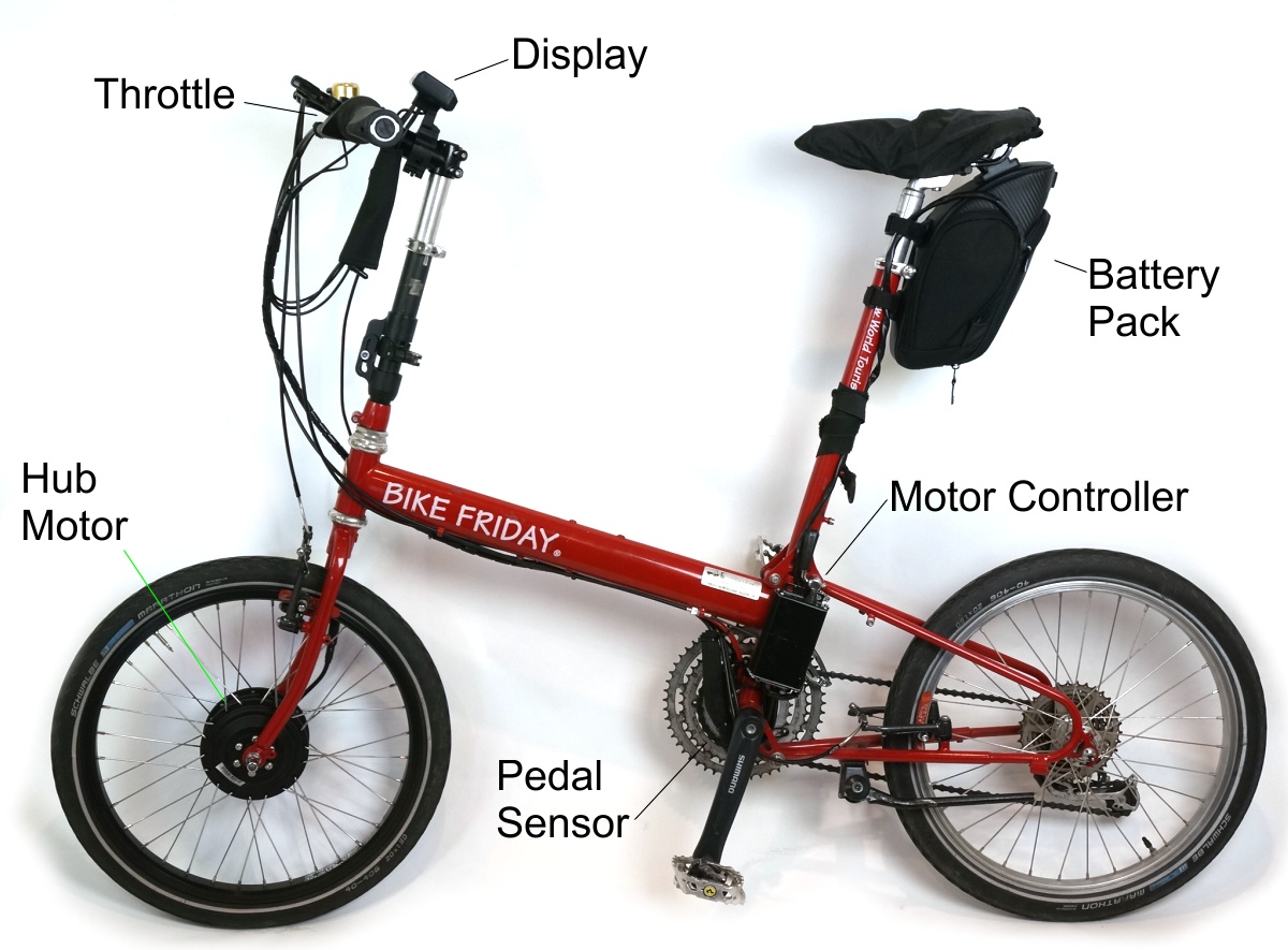
 There are a few critical components (battery, controller, motor) and a number of accessory components (displays, throttles, PAS sensors) that make up an electric bicycle. This article is intended to explain the role of each component to those just learning about ebikes.
The Battery Pack
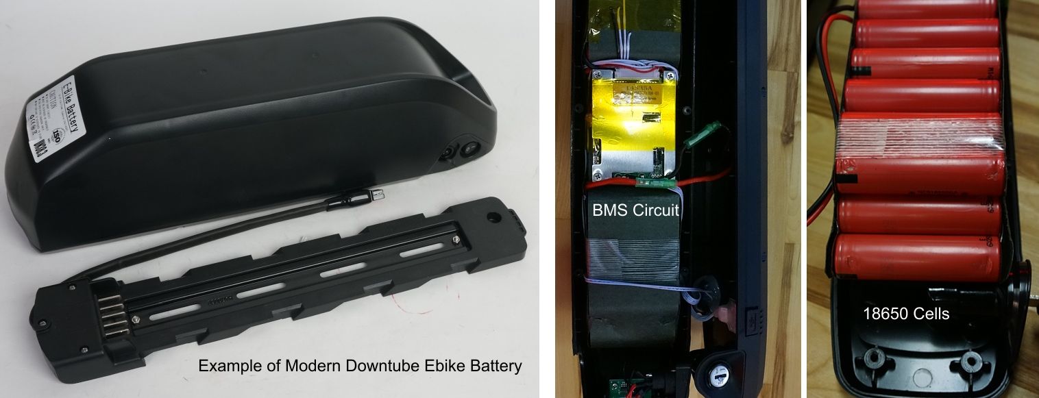
The battery is the energy source that powers an electric bicycle and is typically the most expensive part of an ebike system. In the early days of ebikes most batteries were lead acid, Nickel Cadmium, or NiMH, but modern ebike batteries are almost exclusively lithium-ion. As lithium battery technology matured it got lighter, more powerful, more reliable, and with increasingly long cycle life. It's at a point that now a modern lithium battery made with top-tier cells is 8-10 times lighter than the lead batteries of yesteryear, and when not abused they can be expected to provide well over 5-6 years of regular use.

Lithium packs are made up of many smaller lithium cells connected together into a battery module. While lithium cells are made in many shapes and sizes, every responsible player in this industry has converged on using the small cylindrical format (18650 and slightly larger 21700) cells produced from well renown firms like Panasonic, Sony, Samsung, and LG. These cells have a vastly better safety record and reliability record than generic cells or other lithium types like Lithium-Polymer. In addition to the cells, lithium batteries also require a Battery Management System, or BMS circuit, which senses the voltage on each cell and activates cutoffs to prevent them from being overcharged or overdischarged.
The number of cells in the battery and the way they are wired together in series and parallel determines the voltage and capacity (amp-hours or Ah) of the final pack. Most ebike batteries are wired up for either 36 Volts or 48V, but you will also see ebike packs that are as low as 24V or as high as 72V. Lower voltage systems draw higher current from the pack which can require heavier gauge wires and connectors, while higher voltage systems can get to the point of being an electrocution risk. 36-52V is generally a sweet spot in the tradeoff, totally safe from electrical shock and with low enough amperage draw for inexpensive thin gauge wiring and connectors. That's why most ebikes use this voltage range.
The size or capacity of a battery can be expressed in amp-hours (Ah) or watt-hours (Wh), where the watt-hours is just the amp-hours multiplied by the voltage. It is the watt-hours of a battery that determines the total energy stored inside the pack and hence how much range it will deliver. Most ebike batteries range from 300 to about 800 watt-hours.
It's worth noting that a higher voltage battery will have less amp-hours than a lower voltage battery of the same size. For instance, a 36V 20Ah battery pack (720 watt-hours) is identical in energy storage as a 48V 15Ah battery (also 720 watt-hours). Both packs would be expected to weigh the same and cost the same and provide the same range and power capability when matched to an appropriate motor.
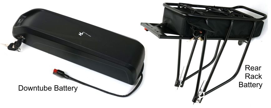
Factory ebikes often integrate the battery pack into the frame tubing of the bike to provide a very tidy external appearance. This seems great until the time comes that the battery needs to be replaced, and the bike model is long discontinued with no one producing that one special shape of battery pack. Conversion kits batteries are usually designed either to mount on the downtube inside the triangle, or on a rear carrier rack. Since they aren't integrated to the bike they can easily be changed around and upgraded down the road.

The Motor
The electric motor turns electrical energy from the battery into mechanical power to move the bike. The motor can be located in many places on a bike but at Grin we focus exclusively on hub motors for the reasons explained here. In a hub motor, the electric motor is inside either the front or rear bicycle hub, allowing for a fairly simple conversion where you replace a regular bike wheel with the motorized wheel. Nearly all ebike motors these days are permanent magnet Brushless DC (BLDC) motors which have 3 phase wires for supplying motor power. In addition to these 3 phase wires to power the hub, they also typically have 5 hall sensor wires that allow the electronics to determine the motor position in order to spin the smoothly at low speed. These wires may be split into separate connectors, or integrated into a single plug that has both the power an signal wires in one.

Hub motors can be geared or direct drive; small and with modest output or large, or heavy and powerful. The optimal motor choice depends very much on the application. Demanding uses like cargo hauling or long steep hill climbs requires larger heavier motors, while people needing just a small boost on mostly flat ground can get away with motors that are light and compact.

The single most important attribute of a motor necessary to understand how it will behave is the motor winding constant in RPM/V, often given the symbol Kv. This tells you the maximum rotational speed of the motor for a given battery voltage, and hence lets you know up to what max speed it will be able to assist a bike. Motor manufacturers can easily produce the exact same motor in a range of winding speeds, and at Grin we usually carry several winding options for each hub model. If a motor winding constant is 10 rpm/V, then that means it will spin at maximum 120 rpm with a 12V battery pack, 240 rpm with a 24V battery pack, 360 rpm with a 36V battery pack and so forth. The table below shows the relation between RPM and vehicle speed for a range of common wheel diameters.
| Wheel Speed | Vehicle Speed for Given Wheel Diameter | ||||
| 16" Wheel | 20" Wheel | 24" Wheel | 26" Wheel | 29" Wheel | |
| 100 RPM | 8 kph | 10 kph | 11 kph | 12 kph | 14 kph |
| 150 RPM | 11 kph | 14 kph | 17 kph | 19 kph | 21 kph |
| 200 RPM | 15 kph | 19 kph | 23 kph | 25 kph | 28 kph |
| 250 RPM | 19 kph | 24 kph | 29 kph | 31 kph | 35 kph |
| 300 RPM | 23 kph | 29 kph | 34 kph | 37 kph | 42 kph |
| 350 RPM | 27 kph | 34 kph | 40 kph | 44 kph | 49 kph |
| 400 RPM | 31 kph | 38 kph | 46 kph | 50 kph | 56 kph |
If you want to have a motor that provides a useful amount of power at any of the speeds in that table, it is crucial to choose a motor winding and battery voltage that is at least 15-20% faster than the running RPM in the table above.
Typical ebike hub motors are wound for around 8 rpm/V, but we usually carry faster winding choices of 10 to 12 rpm/V as well in order to support various applications with smaller wheels diameters and more flexible battery voltages. On our website, we list the RPM/V of each motor winding in the specification table and product description. Unfortunately this information is almost impossible to glean on most other manufacturer and vendor websites.
If you ride the bike faster than the maximum RPM of your motor + battery voltage combination, then either the motor will cease providing any power output (in the case of a geared motor with a freewheel), or it will automatically go into regenerative braking mode (in the case of a direct drive motor) and provide resistance to further speed increases while putting energy into the battery pack.
Controller
The motor controller is a component that is unfamiliar to many people, but it is an essential piece of any ebike hardware since you can't directly connect a brushless motor to a battery pack. The motor controller serves two critical functions
- 1) It converts the DC voltage of the battery pack into 3 phase alternating current for the motor windings without which the motor could not spin, and
- 2) It can continuously adjust the voltage going to the motor, from 0V up to the full battery pack voltage, in response to the user's throttle signal, pedal sensors, and various current limits.
This latter bit is the most vital aspect to understand. The motor controller can reduce the voltage that makes it to the motor to any value between zero and the battery voltage. If you have a 48V battery pack, the voltage that the motor sees might be only 10-12V at low speeds, ~25V at moderate speeds, and only reach 48V when you approach the final cruising speed of the bike. If you have a 48V battery pack and ride at just 50% throttle, then the motor will see 24V, and will perform exactly the same as it would with a 24V battery at full throttle.
It is by varying the voltage to the motor via the controller that you can adjust and modulate the power output of the motor as you ride the bike, which is pretty essential to the idea of controlling an EV. Those with an electronics background should appreciate that the controller acts as an efficient DC-DC buck converter. While it steps down the voltage going to the motor, it simultaneously steps up the current by the same ratio. You can have 48V and 10 amps flowing from the battery into the motor controller, and have 24V and 20 amps flowing from the controller to the motor.

The motor controllers contain at least 6 power mosfets, large capacitors, and connectors for throttles, brake cutoffs, and displays. The controller circuitboard is often fit in an extruded aluminum box, either mounted externally on the bike or tucked inside the chassis somewhere. It's also common to have the motor controller located inside the hub motor or inside the battery mounting cradle. In these latter options, the controller is hidden from view for cleaner ebike with fewer visible components, but it is more challenging to repair or replace a damaged controller when it is integrated this way.
Motor controllers usually have a specific voltage range they they will work in, and they will also have a current limit that defines the maximum amperage that they will draw from the battery pack. A small low current motor controller might be rated for 14 amps, which means it will only draw a maximum of 14 Amps from the battery pack. When the motor attempts to draw more current than this, the controller then automatically reduces the voltage provided to the motor in order to keep the battery current draw right at the limit. If you use a low amperage motor controller with a large hub motor, the system will work fine but you won't be getting nearly as much power from the motor as it is capable of. Conversely, if you use a high amperage motor controller with a small sized motor, then you risk overheating and damaging the motor or stripping the internal gears or clutch.
Those three items, the battery, motor, and controller are the main elements of an ebike system, but there are a number of accessories and add-on components that round out the package
Throttle
A throttle is the most basic and familiar way of allowing the rider to regulate the amount of power they get from the motor by pressing a throttle lever or twisting a grip that is mounted on the handlebar. A throttle gives the rider full control of the amount of power coming from the electric motor at any given time, regardless of how hard they are pedaling.

Almost all controllers have a throttle input plug, and luckily the throttle signal is one of the few things that has been very well standardized in the ebike industry, even if the connectors that they use are all over the map. Virtual all throttles use hall sensors and a magnet to detect the throttle position and sit at about 0.8-0.9V when thee throttle is off, and rise to 3.6-4V as the throttle is engaged.
The two most common throttle types would be categorized as thumb or lever throttles which are actuated by the thumb pushing on a paddle, or twist grip throttles that operate from rotating the a handgrip. Throttles are pretty cheap, and even though they often feel cheap in practice they are quite dependable.
PAS and Torque Sensors
While a throttle lets you control the motor power with your hands, a PAS sensor or Torque sensor allows the ebike to be controlled from your pedaling. Cadence PAS sensors are readily installed on an existing crankset and send signals to the bike whenever you are spinning the pedals, while torque sensors usually require replacing the bottom bracket and measure not only if you are pedaling but also how hard you pushing on the cranks.

Unike throttles, there is very little standardization on how the signals from PAS and Torque sensors should operate, and no easy way to predict whether any given motor controller will have an input for a PAS / Torque sensor, let alone one that matches the signal level of a particular sensor. We've outlined In order to alleviate this compatibility challenges, we have all our pedal sensing devices plug into the Cycle Analyst display so that we can support a broad range of pedal assist systems equally well across all controller models.
Ebrakes
An ebrake sensor is an optional device used to tell the motor controller when you are pressing the brake levers. There are two reasons people would want an ebrake sensor on their ebike. One is to have a safety cutoff, so that no matter what the motor will shut off whenever you press the brake levers. The second reason is to activate regenerative braking on hub motor systems that support regen. That allows you to squeeze the brakes a little bit and have the motor switch from powering the bicycle to providing a smooth an steady braking force, with the braking energy going right back into charging the battery pack.
Both mechanical and hydraulic brake levers are readily available these days with an ebrake switch sensor built right in, while there are also add-on sensors that can be installed on your existing brakes to provide the same switch signal.
Display
Almost all ebike kits and full ebikes these days include a fairly detailed display computer to provide a dashboard to see what's going on. This is a nice enhancement from the early days of ebikes when most systems had just a few LEDs to indicate the battery level. But unlike displays for computers or televisions which have a standard protocol, the displays that connect to ebike motor controllers have no standardization at all either in function, communication bus (I2C, Canbus, LIN, UART, etc), or communication protocol. The displays are generally developed paired with a specific motor controller and for a specific set of kit functions, and it's very rare that you can switch to a different make of motor controller and have it work with your display, or conversely that you could find an alternate display for your particular controller.
At Grin we made a conscious decision early on to avoid this compatibility fiasco by developing our own display in such a way that it doesn't rely on any controller communication. Instead it uses a set of analog signals that can be found already present inside most motor controllers ensuring future controller upgrade-ability. We were hoping that others might follow suite and embrace this approach, but that hasn't quite happened.
An increasing number of controllers will now offer a Bluetooth communication for using a phone as the main display. That is a nice plus feature for sure, but we caution against that being the only display option as phone apps are notorious for having a short window of availability. Odds are slim that a company will still producing a compatible phone app for your hardware 2-3 years from now, let alone 10 years from now.
Torque Arms
On hub motor drives, the torque spinning the wheel forwards produces an equal and oposite torque on the motor axle. Something must brace the axle against rotation or else it will spin backwards. That is the purpose of a torque arm.
Hub motors from China almost universally used an over-sized axle with flat sides to slot in the bicycle and depended on this flat surface to prevent the axle from spinning. That can work up to a point, but with higher power levels or with modern bikes made with alloy or composite materials it's often inadequate. In that case, additional torque arms can be installed over the axle outside the dropout to provide extra spinout protection. Other motors (like our GMAC and All Axle hubs, or all the early non-chinese hubs like Tidalforce, Heinzmann, Sanyo etc) have the torque arm integrated right into the motor axle design. That way it comes as part of the motor and can be engineered for higher strength and easier installation than after-thought torque arms.
Hall Sensors
We bring up hall sensors not because it's an separate part of an ebike system, but because they are often brought up in the troubleshooting and component interchangeability. 3 Phase brushless DC motors typically include three hall sensors that indicate the rotational position of the rotor.
Some simple motor controllers only function when these sensors are present as they use the hall pattern exclusively to time the changing current through the three phase wires. Other more advanced controllers don't use hall sensors at all and do their best to figure out the rotor position and appropriate phase timing based on cues from the current flow and/or voltage on the phase leads. This is called running the motor sensorless. Sensorless operation is fairly easy to sustain when a motor is spinning, but when a motor is stationary or moving very slowly it can be challenging to do well. Finally some controllers use the hall sensors only for starting, and switch to sensorless once the motor is spinning above a certain speed.
When mixing and matching brushless motors and motor controllers it's important know if your motor has hall sensors or not, since that determines which controllers may or may not be compatible.


 Canadian