Frankenrunner

Introduction
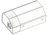
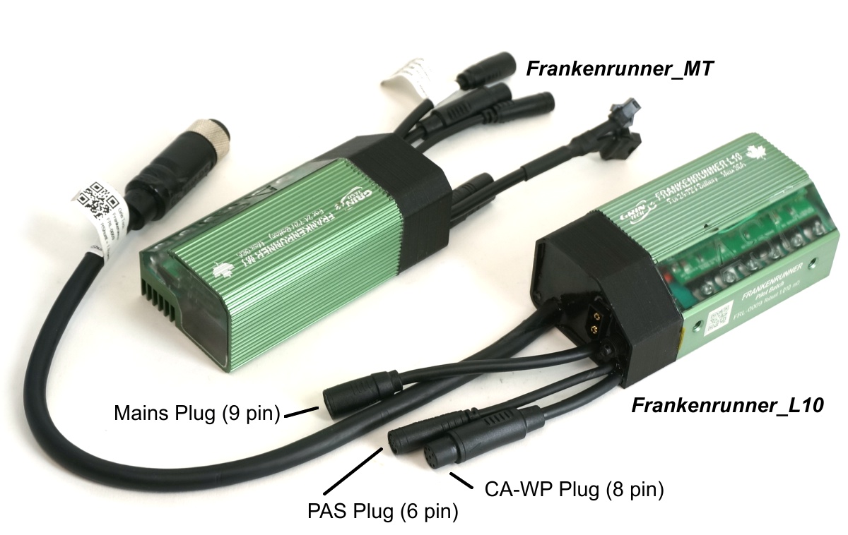 The Frankenrunner is a field-oriented controller that Grin has introduced in 2022 as a stop-gap substitute for the popular Phaserunner device. It is based around a stock ASI BAC855 with all of our Phaserunner modifications tacked onto the end rather than embedded in a custom enclosure. While not quite as slick and compact, it still delivers the same punch, and boasts all the updated features that will be present in the V4 Phaserunner devices too. That includes all waterproof signal connectors, a 9 pin OEM main cable to support the use of certain 3rd party displays, support for motor temperature sensors, and direct attachment of PAS or Torque sensors.
This controller was designed as a universal device that can fit on almost any bicycle frame and handle almost any motor system in the 500-2000 watt power range. You can power it from a 24V battery or a 72V battery, and run your phase current to peaks of over 90 amps, though the continuous current capability without additional heatsinking is typically 45-50A. The Frankenrunner_L10 has a cable exit for compatibility with all the motors supplied by Grin with the L1019 connector, while the Frankenrunner_MT is connectorized for separate cable harnesses between the controller and motor.
Features
- Wide Operating voltage range from 20V to 86V (20S Li-Ion, 24s LiFe)
- Remote on/off switch compatible
- Compatible with CA3-WP display and control device
- Proportional regen available through throttle signal or stand alone wire
- Works both Sensored and Sensorless, and even with very high eRPMs
- Waterproof, 100% potted electronics
- Fully programmable parameters (regen voltage, max phase and battery currents etc.)
- Field Weakening allows you to run motors faster than normal back-emf limit
- Virtual Electronic Freewheeling allows you to experience zero drag with direct drive motors
- Higher motor efficiency than typical trapezoidal controllers
- Torque based throttle command (no twitchy throttle with powerful system)
- Automatic thermal rollback to prevent controller overheating
Connector Pinouts
Both models of the Frankenrunner use the same connectors for the Battery, Cycle Analyst, Throttle, and Communication plugs, but they differe in how they hook up to the motor.
 |
Battery - XT60: The hookup for the battery pack is with an embedded XT60 style male bullet connector. Each Frankenrunner includes an 80cm battery cable terminated with an XT60 female plug at one end and Anderson Powerpoles on the other for hookup to your battery pack. We recommend not using the XT60 plug for making a live connection to the battery as the inrush current spark to the controller capacitors can damage the gold plated bullet plugs. |
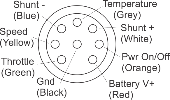 |
CA3 Display - WP8: The Frankerunner uses the waterproof WP8 Cycle Analyst plug standard which includes motor temperature and on/off power lines to the CA3. Please use the WP8->JST adapter for use with older models of Cycle Analyst using the 6-pin JST-SM plug. |
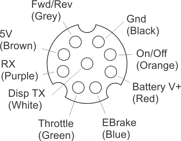 |
Mains Connector: A 9 pin plug provides all the signals needed for conventional ebike wiring harness strategies where the throttle and ebrake connect to the motor controller and a 3rd party display has the on/off power and communicates the assist level. For the controller to turn on, the key input on either the Mains or CA plugs must be shorted to V+. |
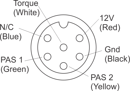 |
PAS Connector: A 6 pin HiGo plug provides an input for the direct hookup of either PAS or Torque sensors to the motor controller. This is required for pedalec ebikes that don't use a Cycle Analyst. With a Cycle Analyst system this plug is not used as the PAS sensors, throttles, and all accessories plug into the CA3 instead. |
| Communications - TRRS: The Frankenrunner uses a TRRS jack to support communication to computers and smart phones using our USB->TTL adapter cable. As shipped there is a rubber plug to seal this jack from water. Some customers have reported iffy communication with the built-in port, in which case we also offer a 9-pin->TRRS adapter |
L10 Particulars
The only additional wire on the Frankenrunner_L10 is the motor cable, which is 40cm long and terminated with the female L1019 plug for a rugged connection to Grin motors that use this connector standard
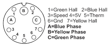 |
Motor - L1019: The motor connection on the Frankenrunner_L10 is through the locking and waterproof Higo L1019 plug or the Cusmade equivalent. The cable uses 3mm^2 (12 awg) wire for the 3 motor phase leads to support high amperage, and has a total of 7 smaller gauge signal connectors. Five of these are used for the hall signals and power, while the extra two serve for the motor temperature sensor (grey) and a wheel speed sensor (white). |
MT Particulars
On the Frankenrunner_MT, the hookup between the motor and the controller is done via 3 separate plugs rather than through a single cable with an overmolded connector.
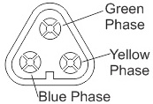 |
Motor Phase - MT60: The 3 motor phases are terminated with a male MT60 bullet connector. This compact plug supports high phase amperages in a very small connector size. |
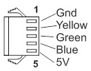 |
Motor Hall - JST-SM: The hall plug is a 5 pin female JST connector using the same pinout standard we adopted since 2008. |
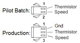 |
Speed/Thermistor Pass Thru - JST-SM: The final female JST-SM plug is present in order to hook up additional motor temperature and wheel speed signals. In the pilot batch Frankenrunners this was a 2-pin JST plug, and it was updated to 3-pin for the production run to provide a convenient additional ground pin. If the motor has a built in temperature sensor, this signal can be fed to JST Pin1 to show motor temp on the CA3 and enable thermal rollback. Geared motors that have an internal speed sensor should use Pin2 as a pass-thru of the speedometer signal line to get speed display on the CA3. Mid-drive and geared motors without speed sensors should have an external speed sensor attached. If a direct drive motor is used with no speed sensor, the setting at address 174 "HDQ Replicating Hall" can be checked for a speed reading to appear. |
Additional Cables
With the Frankenrunner_MT, we provide the following optional motor cable harnesses for different motor applications. The Anderson terminated cable is compatible with our hub motors sold from 2019 and earlier and is recommended for 3rd party motors for which there isn't another compatible plug type
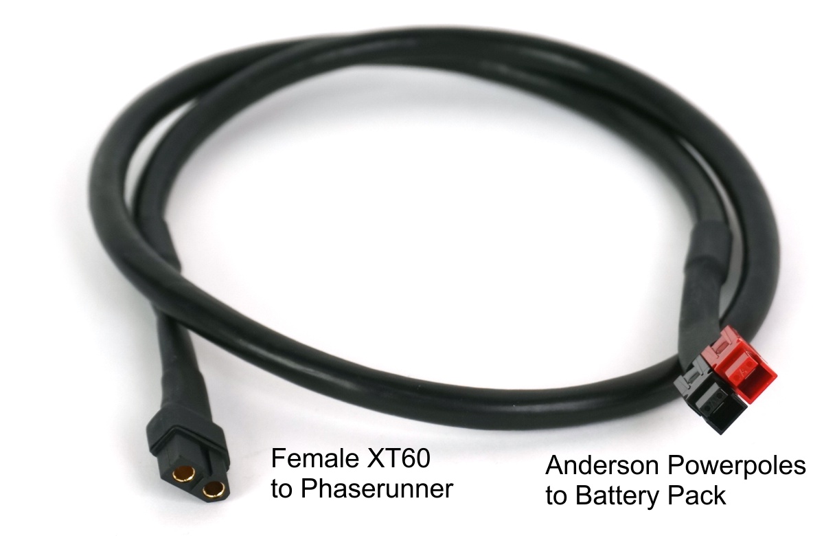 |
Battery Cable: Both Frankenrunner models come stock with an 80cm long XT60 to Anderson battery cable for mating with batteries that use Anderson Powerpoles. |
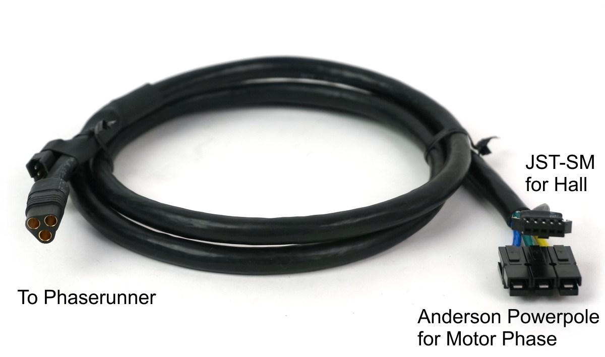 |
Stock Motor Harness: The standard motor cable has staggered MT60 + male JST-SM connectors on the controller end and Anderson + female JST-SM connectors for the motor. This is compatible with all of the medium to high power hub motors that Grin has sold since about 2009, and is available in both a short (45cm) and long (120cm) cable length option. Note that the Frankenrunner is capable of delivering high enough continuous phase current to melt the Anderson plugs, and we don't recommend using this connector in applications that will be sustaining more than 70 amps of phase current for extended periods. |
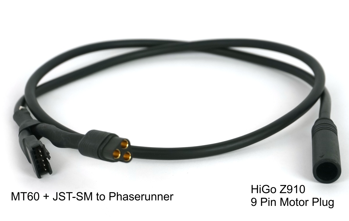 |
HiGo Z910 Motor Harness: This cable harness terminates at the motor end with the 9 pin waterproof HiGo motor plug popular in many lower power hub motors. We recommend limiting the phase current to no more than 50 amps with this connector harness and plug standard. Notice that if the motor has a speedometer sensor built in, that signal will not be connected to the Phaserunner's CA Plug and you will need to use a CA with an external speedo.; |
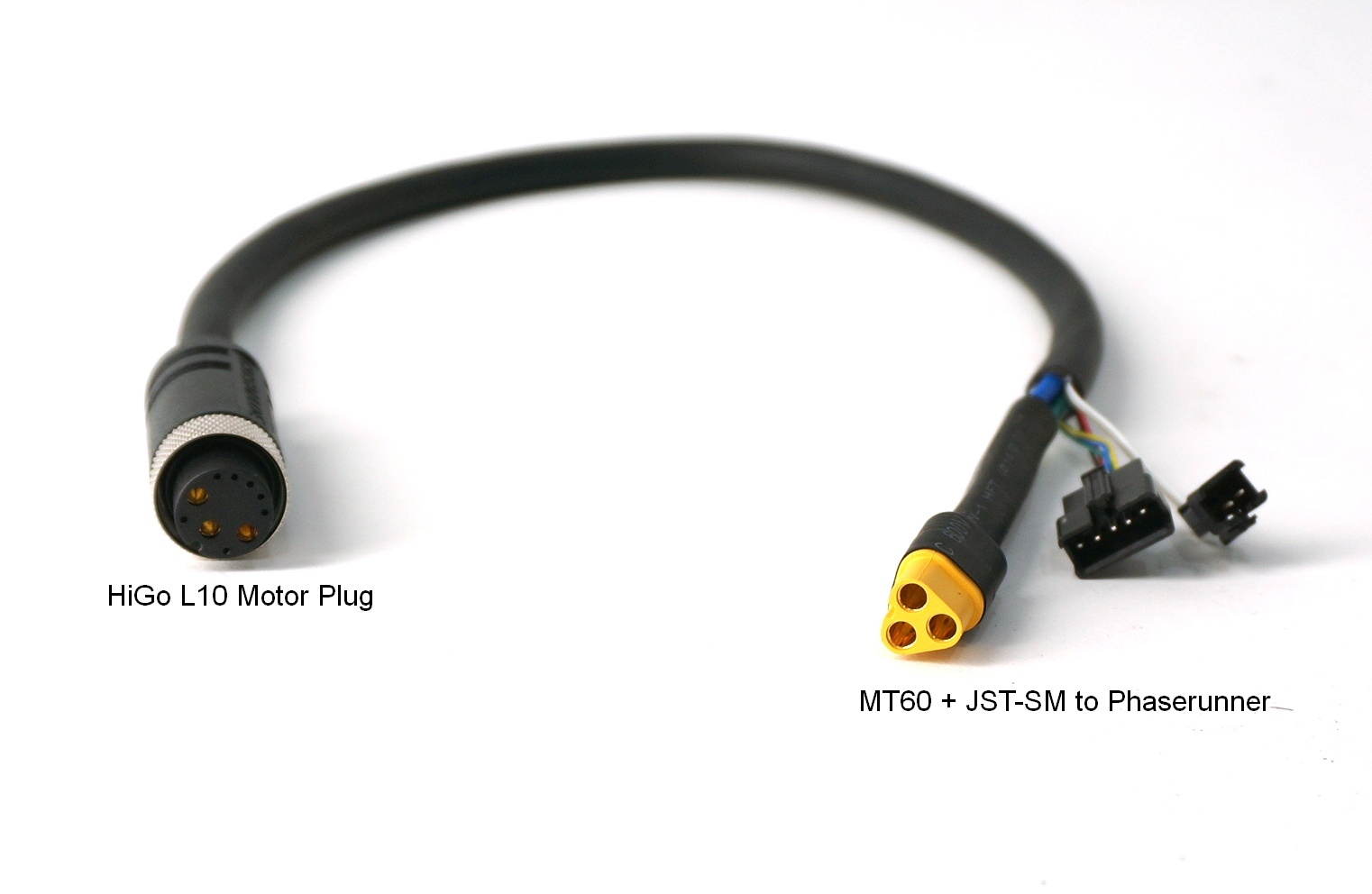 |
L1019 Motor Harness: This cable harness can be used to connect the Frankenrunner_MT controller to hub motors that use the L1019 plug standard. In general we recommend the Phaserunner_L10 model in this application, but we made this for customers who already have a Frankenrunner_MT and now want to use it on a new motor with the L1019 connector. |
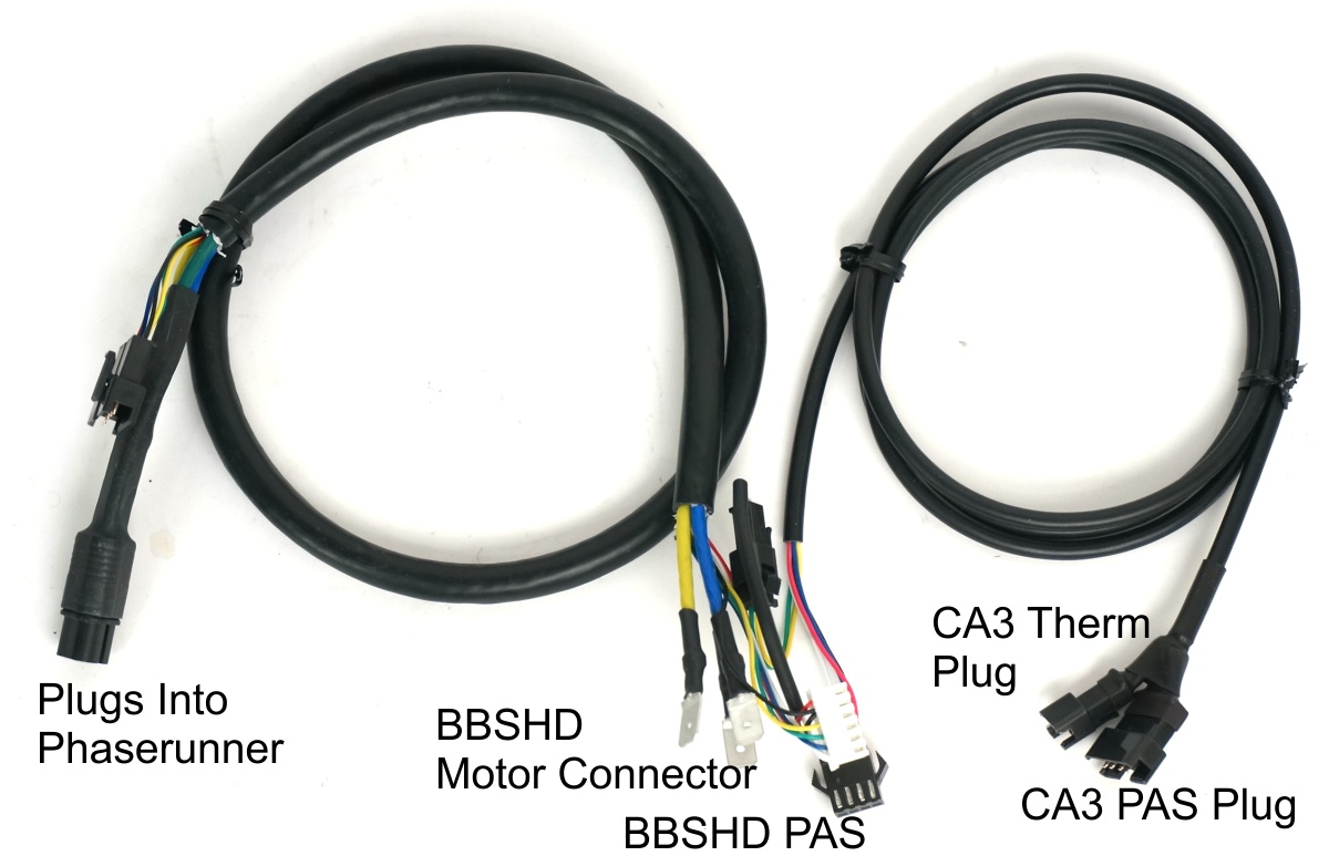 |
BBSHD Motor Harness: -ON PAUSE- The original BBSDH harness we had made up for the Phaserunner units is not as plug and play compatible with the Frankenrunner and the CA3-WP devices. We will be revisiting and revising this product and should have an updated cable harness assembly available in July. |
The following accessory cables are also available with the Frankenrunner.
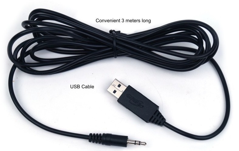 |
USB to TTL Cable: The USB->TTL communication cable is required to connect the Frankenrunner controller to a computer in order to change and update settings. This is the same FTDI-based serial cable with a TRRS jack we use for the Satiator and Cycle Analyst. |
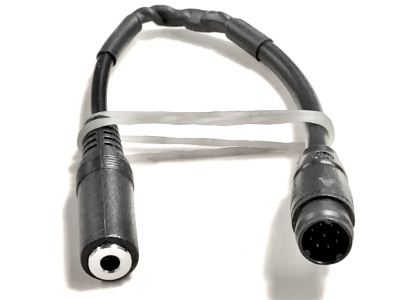 |
9 Pin Main to TRRS: Occasionally people have damaged the main TRRS port on their Frankenrunner or debris inside the port has rendered it unreliable. This adapter provides an alternative access point to communicate with the Frankenrunner via the Tx and Rx communication lines present on the 9 pin mains plug. |
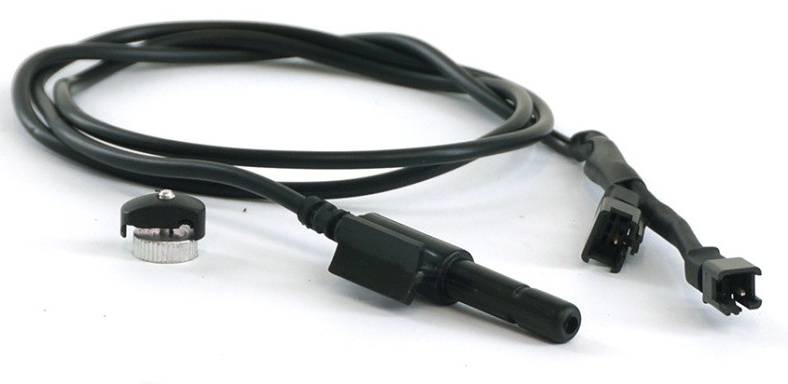 |
Speedometer Cable: A separate spoke magnet based speed sensor is required with mid-drive systems or geared motors that lack an internal speed sensor. This connects to the 3 pin JST plug on the Frankenrunner_MT device and provides a separate 2 pin plug for hooking up a motor thermistor if desired. This product is not compatible with the Frankerunner_L10 which expects there to be wheel speed signaling present in the L1019 connector. |
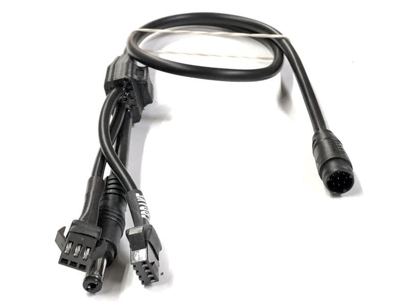 |
9 Pin Basic Mains Cable: This cable harness is required if you are not using a V3 Cycle Analyst device with the Frankerunner. It provides a 3 pin throttle plug, a 4 pin ebrake plug, and a DC jack for running front lights. As well, it shorts together the on/off switch wires so that the controller is powered on with battery power. |
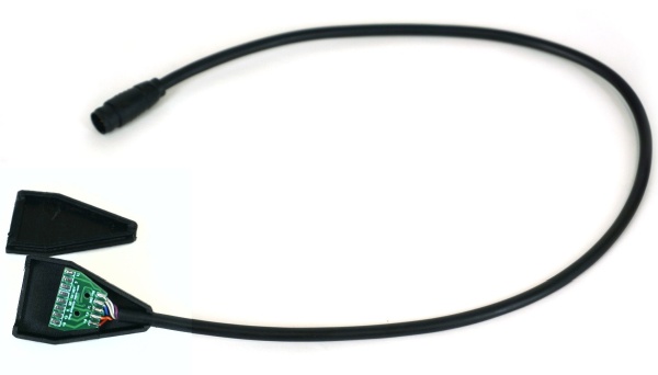 |
9 Pin DIY Mains Cable: For more advanced users, we also provide a bare PCB version of the 9 pin mains cable that allows you to custom solder in place your own throttle, ebrake, on/off switch, fwd/rev switch wires with any connector and cable length of your choosing. This also has pads for the Tx and Rx communication signaling when using 3rd party displays that operate with the KM5s protocol. Once soldered the PCB should be fully encapsulated in conformal coating or potting resin to waterproof the junction. IMPORTANT NOTE: High levels of care are required to ensure that the V+ battery voltage wire is not inadvertently shorted to one of the other signal wires. This can cause permanent and telltale hardware failure of the Frankenrunner controller and is not covered by warranty. Be sure to do all soldering and cable harness prep without the cable connected to the motor controller, and only hook it up to the controller when you are confident in your workmanship. |
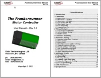
User Manual
CAD Files
Software Suite
Phaserunner Suite, Windows, Portable
Phaserunner Suite, Windows, Installer
Phaserunner Suite, macOS (Requires macOS 10.13 or newer)
There is also a version for Android that is in development, and available for beta testers on the Google Play Store. This requires the use of a USB OTG compatible device, as well as a USB OTG adapter to connect our USB->TTL programming cable to the micro USB or USB-C connector present on most smartphones.
The drivers for the FTDI chipset inside the USB-TTL adapter can be found through FTDI here - https://www.ftdichip.com/Drivers/VCP.htm
Videos
Troubleshooting
Most tech savvy people are able to setup and tune the Frankenrunner with relative ease using our software suite and following the direction in the user manual. Here are some of the more common troubleshooting issues that we have run into doing tech support.
Controller Not Turning On: The most common reason for this is that the on/off switch wiring is not wired up to turn the device on. This is accomplished either with a Cycle Analyst plugged into the WP8 plug, or one of the 9 pin mains cable options on the 9 pin plug. If you apply battery power to the controller without something to short together the key switch to V+ on one of these two plugs then it will not power on and cannot be hooked up to a computer.
Unreliable Communications: There are instances of people having difficulty establishing regular computer communications to the Frankerunner via the built-in TRRS port. The exact cause for this is still under investigation, but in these cases, we recommend using the Tx and Rx pins that are present in the 9-pin mains cable, and we offer a simple adapter to provide this.
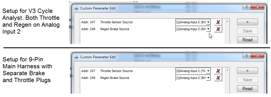
No Response to Throttle: The Frankenrunner controller can be configured so that the throttle input signal is mapped either to Analog Input 1 (Throttle), or Analog Input 2 (Brake1). The throttle output signal of the Cycle Analyst on the WP8 plug is wired to the Analog Input 2 (Brake1) signal source, as that allows the Cycle Analyst to activate throttle and regen from a single wire. If you are using the 9pin mains cable, then typically you will want separate input signal wires for the throttle and the regen brake. In these cases, the throttle source must set to Analog Input 1, and the regen brake source to Analog Input 2. This is done via the custom parameter edit menu as shown in the image below.
Instantaneous Phase Overcurrent Fault (2-2 Flash): This is a fault that typically occurs when the motor tuning parameters are not well matched to the motor. It will occur all the time if a user didn't bother to either load the correct motor defaults or run both the static and dynamic autotune. With motors that have been run through autotune successfully, it sometimes occurs when there is a sudden change in the motor eRPM (such as hitting a pothole, or the motor transitioning from open loop to closed loop sensorless operation), and it usually means that the current regulator bandwidth and/or the PLL bandwidth are not high enough to track the dynamic motor response. Increasing both the PLL and Current Regulator in tandem will usually result in setting that doesn't result in phase overcurrent faults. In some cases where this tuning along is not sufficient, then the currently regulator Ki and Kp terms can be adjusted independently.
POST Static Gate Fault (1-8 Flash): This fault occurs if there is substantial stray electrical conductivity detected between one of the phase wires and either the V+ or Gnd bus. It will occur if there is a blown mosfet, if the motor wire is nicked at the axle and is shorting a phase lead to the motor casing, or if water has ingressed inside the motor causing paths for electrical connectivity with the phase wires. If this message shows up, disconnect the Frankenrunner from the motor, apply the throttle, and look at each of the phase open circuit voltages from the edit parameter menu. They should be around 0.5 Vnom and if so the issue is likely in your motor. If you see a value of 0.00 or 1.00 Vnom, then there is a damaged mosfet.
Damaged XT60 Connector: We've seen several instances with high power rigs where the XT60 plug for the battery cable has become badly damaged from arcing, sometimes even melting the contacts. The battery current draw on the Frankenrunner is much lower than what the XT60 contacts are rated for, so we believe that this failure is mostly the result of mechanical stresses on the battery leads pulling the connector at an angle and causing interruptions and arcs in the power flow. It's possible to spread apart the 4 tongs of the male pin for a tighter mechanical contact, and we recommend ensuring that the battery cable is not being tugged (eg by cable ties) in such a way that it pulls the connector at an angle. Instead the battery connector/cable should float freely with a 'Z' bend to the frame so that it stays aligned and in good contact.
Native PAS and Third Party Displays
In principle the Frankenrunner can be configured to use certain conventional ebike displays instead of the Cycle Analyst. In particular displays using the KM5s protocol (originally from King Meter) seem to be mostly well-behaved. This configuration also requires the Pedal cadence or torque sensor to plug into the Frankenrunner directly via the 6 pin HiGo connector, with all the PAS and torque control settings and assist levels configured within the controller's setting framework.

Unfortunately this configuration is far less intuitive to setup than it is with the Cycle Analyst device, and is not something we can support at the retail level. We are still entertaining this with certain OEM customers, and are working on a custom version of our Phaserunner software suite to facilitate the otherwise cumbersome setup process. In the meantime though, assume a CA3-WP display is required if you want torque/PAS assist modes.
Support Limitations
We give full warranty and support whenever the Frankenrunner is purchased as part of a kit system from Grin and everything will come pre-configured. But we are limited in the help we can provide for people purchasing just the controller from us and then hooking it up to a third party motor system. We've found a number of people have purchased the device without first looking into what the setup entails, both from a hardware and wiring perspective and also from a motor tuning perspective. Then they get in over their head, or do silly things. Please read everything in the user manual and on this webpage, and watch our related videos before purchasing. If after that you think "Yes that's totally in my wheelhouse" then great. Otherwise we'd recommend looking elsewhere for something with a narrower scope that is more plug-and-play for your particular system. A very generalized and configurable item like the Frankenrunner by its very nature cannot be "plug-and-play".
Additional Details
We posted a fair amount of our test data in the endless-sphere forum during the development and initial pilot roll-out of the Phaserunner controller, and we've highlighted some of this data here. The Frankenrunner is identical in all respects:
- Efficiency comparison: Here we did direct comparisons on our dyno of a standard Infineon trapezoidal controller versus the Phaserunner controller running the same hub motor with the same battery current. You can see upwards of a 5% improvement in motor efficiency with the Phaserunner hub, as well as a steeper drop off in torque vs RPM
- Field Weakening: Here are some discussions of the field weakening capability of the Phaserunner and how that affects both the no-load current draw and the unloaded RPM.
- eRPM Limit: Here we showed the Phaserunner controller running an RC outrunner motor at 72,000 eRPM's. However, ASI advised that beyond 60,000 eRPM the controller performance can suffer and we only did the testing unloaded.
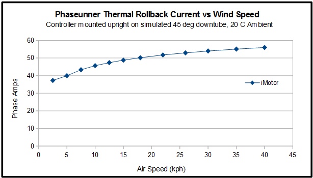
- Thermal Rollback Limits: While the Fankenrunner can put out 96 amps of phase current for short periods, within several minutes the heatsink will reach over 80 degrees and thermal rollback will kick in, automatically reducing the maximum phase amps. The maximum continuous phase current depends on installation details and air flow but is typically between 50-55A. The chart below shows the measure thermal rollback current of a Phaserunner when mounted with no additional heatsink to the downtube of a bicycle. Since the Frankerunner has more metal and exposed fins than the Phaserunner we expect the performance to be even a bit better. If the controller is placed inside an insulated cavity or bag with no airflow at all then the continuous current can be much lower, around 30A.
Where to Order
Frankerunner controllers are available individually from our store page (both the L10 and MT models) or as part of the High Voltage and DIY conversion kit bundles. We are manufacturing the devices daily and there is currently a ~1-2 week order backlog before a unit purchased now will be complete and ready to ship.


 Canadian

 Grin Tech Online Store